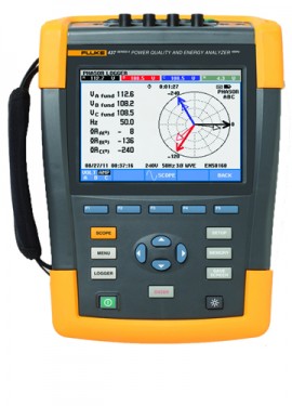
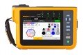
Help locate, predict, prevent, and troubleshoot power quality problems in three-phase and single-phase power distribution systems with this energy analyzer. This unit's measurement process and data output are optimized to help you easily access important information. Additionally, it features an energy loss calculator.
Help locate, predict, prevent, and troubleshoot power quality problems in three-phase and single-phase power distribution systems with this energy analyzer. This unit's measurement process and data output are optimized to help you easily access important information. Additionally, it features an energy loss calculator.
Discontinued!
This product has been discontinued and is no longer available.
There is no direct replacement, however we recommend the:
Not what you're looking for? Let’s do a search and help you find what you need.
Built to help users minimize downtime, quickly troubleshoot power quality issues, and easily discover the costs of wasted energy. Downtime is costly therefore, acquiring data you need to solve to critical power quality issues quickly is key. This unit's measurement process and data output are optimized to aid you to access critical information easily.
Multiple parameters are measured simultaneously and displayed in formats that quickly describe overall power quality health. The detailed information helps you make better maintenance decisions—whether you're trying to reduce energy waste, find the source of power quality issues or see how motor startups are affecting your electrical system. Data can be accessed as simple digital values, trend graphs (for fast insight into changes over time), waveforms, or phasor diagrams. The data can also be analyzed and organized into tabular formats. Detailed event data allows you to see the magnitude, duration and time stamping of anomalies enabling you to rapidly correlate the problems you are experiencing in your facility.
Features
Unified power measurement
The patented Unified Power Measurement system (UPM) provides the most comprehensive view of power available, measuring:
These UPM calculations are used to quantify the fiscal cost of energy loss caused by power quality issues. The calculations are computed, along with other facility-specific information, by an Energy Loss Calculator that ultimately determines how much money a facility loses due to wasted energy.
Energy savings
Traditionally energy savings are achieved by monitoring and targeting, or in other words, by finding the major loads in a facility and optimizing their operation. The cost of power quality could only be quantified in terms of downtime caused by lost production and damage to electrical equipment. The unified power measurement (UPM) method now goes beyond this to achieve energy savings by discovering the energy waste caused by power quality issues. Using the unified power measurement, the energy loss calculator (see screen shot below) will determine how much money a facility is losing due to waste energy.
Unbalance
UPM gives a more comprehensive breakdown of the energy consumed in the plant. In addition to measuring reactive power (caused by poor power factor), UPM also measures the energy waste caused by unbalance; the effect of unevenly loading each phase in three-phase systems. Unbalance can often be corrected by reconnecting loads on different phases to ensure the current drawn on each phase is as equal as possible. Unbalance can also be corrected by installing an unbalance reactance device (or filter), that will minimize the effects. Correcting unbalance should be basic good housekeeping in the facility as unbalance problems can cause motor failure or shorten equipment life expectancy. Unbalance also wastes energy. Using UPM can minimize or eliminate that energy waste, thus saving money.
Harmonics
UPM also provides details of the energy wasted in your facility due to the presence of harmonics. Harmonics may be present in your facility due to the loads you operate or may be caused by loads in adjacent facilities. The presence of harmonics in your facility can lead to:
Quantifying the cost of wasted energy due to the presence of harmonics simplifies the return-on-investment calculation needed to justify purchasing harmonic filters. By installing a harmonic filter the ill effects of harmonics can be reduced and energy waste eliminated, resulting in lower operational costs and more reliable operation.
| Volt | |
| Vrms (AC + DC) | Measurement Range: 1 to 1000 V phase to neutral Resolution: 0.1 V Accuracy: ±0.1% of nominal voltage |
| Vpk | Measurement Range: 1 to 1400 Vpk Resolution: 1 V Accuracy: 5% of nominal voltage |
| Voltage Crest Factor (CF) | Measurement Range: 1.0 > 2.8 Resolution: 0.01 Accuracy: ±5% |
| Vrms1⁄2 | Measurement Range: 1 to 1000 V phase to neutral Resolution: 0.1 V Accuracy: ±1% of nominal voltage |
| Vfund | Measurement Range: 1 to 1000 V phase to neutral Resolution: 0.1 V Accuracy: ±0.5% of nominal voltage |
| Amps (AC + DC) | |
| i430-Flex 1x | Measurement Range: 5 to 6000 A Resolution: 1 A Accuracy: ±0.5% ±5 counts |
| i430-Flex 10x | Measurement Range: 0.5 to 600 A Resolution: 0.1 A Accuracy: ±0.5% ±5 counts |
| 1mV/A 1x | Measurement Range: 5 to 2000 A Resolution: 1 A Accuracy: ±0.5% ±5 counts |
| 1mV/A 10x | Measurement Range: 0.5 to 200 A (AC only) Resolution: 0.1 A Accuracy: ±0.5% ±5 counts |
| Apk | |
| i430-Flex | Measurement Range: 8400 Apk Resolution: 1 Arms Accuracy: ±5% |
| 1mV/A | Measurement Range: 5500 Apk Resolution: 1 Arms Accuracy: ±5% |
| A Crest Factor (CF) | |
| Measurement Range | 1 to 10 |
| Resolution | 0.01 |
| Accuracy | ±5% |
| Amps1⁄2 | |
| i430-Flex 1x | Measurement Range: 5 to 6000 A Resolution: 1 A Accuracy: ±1% ±10 counts |
| i430-Flex 10x | Measurement Range: 0.5 to 600 A Resolution: 0.1 A Accuracy: ±1% ±10 counts |
| 1mV/A 1x | Measurement Range: 5 to 2000 A Resolution: 1 A Accuracy: ±1% ±10 counts |
| 1mV/A 10x | Measurement Range: 0.5 to 200 A (AC only) Resolution: 0.1 A Accuracy: ±1% ±10 counts |
| Afund | |
| i430-Flex 1x | Measurement Range: 5 to 6000 A Resolution: 1 A Accuracy: ±0.5% ±5 counts |
| i430-Flex 10x | Measurement Range: 0.5 to 600 A Resolution: 0.1 A Accuracy: ±0.5% ±5 counts |
| 1mV/A 1x | Measurement Range: 5 to 2000 A Resolution: 1 A Accuracy: ±0.5% ±5 counts |
| 1mV/A 10x | Measurement Range: 0.5 to 200 A (AC only) Resolution: 0.1 A Accuracy: ±0.5% ±5 counts |
| Hz | |
| Fluke 434 at 50 Hz Nominal | Measurement Range: 42.50 to 57.50 Hz Resolution: 0.01 Hz Accuracy: ±0.01 Hz |
| Fluke 434 at 60 Hz Nominal | Measurement Range: 51.00 to 69.00 Hz Resolution: 0.01 Hz Accuracy: ±0.01 Hz |
| Power (Watts (VA, var) | |
| i430-Flex | Measurement Range: Max 6000 MW Resolution: 0.1 W to 1 MW Accuracy: ±1% ±10 counts |
| 1 mV/A | Measurement Range: Max 2000 MW Resolution: 0.1 W to 1 MW Accuracy: ±1% ±10 counts |
| Power Factor (Cos j/DPF) | Measurement Range: 0 to 1 Resolution: 0.001 Accuracy: ±0.1% at nominal load conditions |
| Energy | |
| kWh (kVAh, kvarh) | Model: i430-Flex 10x Measurements and resolution: Depends on clamp scaling and V nominal Accuracy: ±1% ±10 counts |
| Energy Loss | Model: i430-Flex 10x Measurements and resolution: Depends on clamp scaling and V nominal Accuracy: ±1% ±10 counts Excluding line resistance accuracy |
| Harmonics | |
| Harmonic Order (n) | DC, 1 to 50 Grouping: Harmonic groups according to IEC 61000-4-7 |
| Inter-Harmonic Order (n) | OFF, 1 to 50 Grouping: Harmonic and Interharmonic subgroups according to IEC 61000-4-7 |
| Volts % (f) | Measurement Range: 0.0 to 100% Resolution: 0.1% Accuracy: ±0.1% ±n x 0.1% |
| Volts % (r) | Measurement Range: 0.0 to 100% Resolution: 0.1% Accuracy: ±0.1% ±n x 0.4% |
| Volts % (Absolute) | Measurement Range: 0.0 to 1000 V Resolution: 0.1 V Accuracy: ±5% |
| Volts % (THD) | Measurement Range: 0.0 to 100% Resolution: 0.1% Accuracy: ±2.5% |
| Amps % (f) | Measurement Range: 0.0 to 100% Resolution: 0.1% Accuracy: ±0.1% ±n x 0.1% |
| Amps % (r) | Measurement Range: 0.0 to 100% Resolution: 0.1% Accuracy: ±0.1% ±n x 0.4% |
| Amps % (Absolute) | Measurement Range: 0.0 to 600 A Resolution: 0.1 A Accuracy: ±5% ±5 counts |
| Amps % (THD) | Measurement Range: 0.0 to 100% Resolution: 0.1% Accuracy: ±2.5% |
| Watts % (f or r) | Measurement Range: 0.0 to 100% Resolution: 0.1% Accuracy: ±n x 2% |
| Watts % (Absolute) | Measurement Range: Depends on clamp scaling and V nominal Accuracy: ±5% ±n x 2% ±10 counts |
| Watts % (THD) | Measurement Range: 0.0 to 100% Resolution: 0.1% Accuracy: ±5% |
| Phase Angle | Measurement Range: -360 to 0° Resolution: 1° Accuracy: ±n x 1° |
| Flicker | |
| Plt, Pst, Pst (1 min) Pinst | Measurement Range: 0.00 to 20.00 Resolution: 0.01 Accuracy: ±5% |
| Unbalance | |
| Volts % | Measurement Range: 0.0 to 20.0% Resolution: 0.1% Accuracy: ±0.1% |
| Amps % | Measurement Range: 0.0 to 20.0% Resolution: 0.1% Accuracy: ±1% |
| Mains Signaling | |
| Threshold Levels | Threshold, limits and signaling duration is programable for two signaling frequencies |
| Signaling Frequency | Measurement Range: 60 to 3000 Hz Resolution: 0.1 Hz |
| Relative V % | Measurement Range: 0 to 100% Resolution: 0.1% Accuracy: ±0.4% |
| Absolute V3s (3 Second Average) | Measurement Range: 0.0 to 1000 V Resolution: 0.1 V Accuracy: ±5% of nominal voltage |
| General Specifications | |
| Operating Temperature | 32 to 104°F (0 to 40°C) 32 to 122°F (0 to 50°C) excluding battery |
| Storage Temperature | -4 to 140°F (-20 to 60°C) |
| Humidity | 95% RH non-condensing at 50 to 86°F (10 to 30°C) 75% RH non-condensing at 86 to 104°F (30 to 40°C) 45% RH non-condensing at 104 to 122°F (40 to 50°C) |
| Maximum Operating Altitude | Up to 6666' (2000 m) for CAT IV 600 V, CAT III 1000 V Up to 10,000' (3000 m) for CAT III 600 V, CAT II 1000 V Maximum storage altitude 40,000' (12 km) |
| Electro-Magnetic-Compatibility (EMC) | EN 61326 (2005-12) for emission and immunity |
| Interfaces | Mini-USB-B, Isolated USB port for PC connectivity SD card slot accessible behind instrument battery |
 |  |  | |
| Model | Fluke 434-II | Fluke 435-II | Fluke 437-II |
|---|---|---|---|
| Standard compliance | IEC 61000-4-30 Class S | IEC 61000-4-30 Class A | IEC 61000-4-30 Class A |
| Volt Amp Hz | |||
| Dips and swells | |||
| Harmonics | |||
| Power and energy | |||
| Energy loss calculator | |||
| Unbalance | |||
| Monitor | |||
| Inrush | |||
| Event waveform capture | |||
| Flicker | |||
| Transients | |||
| Mains signaling | |||
| Power wave | |||
| Power inverter efficiency | |||
| 400Hz | |||
| C1740 Soft Case | |||
| C437-II Hard Case with rollers | |||
| SD card (Max 32 GB) | 8 GB | 8 GB | 8 GB |
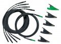
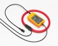
All models include the following accessories TL430 test lead set, 4 x i430 thin flexi current probes, BP290 battery, BC430 power adapter with international power adapter set, USB cable A-B mini and PowerLog CD.
Perform custom analysis and create reports with included software. Measurement data can also be exported to common spreadsheet programs.

Designed to quickly view recorded data, the included Power Log software displays all recorded parameters on interactive trends. Generate a professional report with the 'Report Writer' function, or copy and paste images into report document manually.
FlukeView Power Quality Analyzer Software (SW43W) offers you simple mouse-controlled tools to work with your Power Quality Analyzer.
The FlukeView software communicates with your Power Quality Analyzer via the optically isolated OC4USB adapter/cable connected to the USB of the PC. The OC4USB driver creates a virtual COM port. FlukeView will handle the USB port as a COM port.
Note:
The optional RS-232 adapter/cable PM9080 allows you to communicate via a COM port of your PC.
Click on a category to view a selection of compatible accessories with the Fluke 434-II Three-Phase Energy Analyzer.


| Volt | |
| Vrms (AC + DC) | Measurement Range: 1 to 1000 V phase to neutral Resolution: 0.1 V Accuracy: ±0.1% of nominal voltage |
| Vpk | Measurement Range: 1 to 1400 Vpk Resolution: 1 V Accuracy: 5% of nominal voltage |
| Voltage Crest Factor (CF) | Measurement Range: 1.0 > 2.8 Resolution: 0.01 Accuracy: ±5% |
| Vrms1⁄2 | Measurement Range: 1 to 1000 V phase to neutral Resolution: 0.1 V Accuracy: ±1% of nominal voltage |
| Vfund | Measurement Range: 1 to 1000 V phase to neutral Resolution: 0.1 V Accuracy: ±0.5% of nominal voltage |
| Amps (AC + DC) | |
| i430-Flex 1x | Measurement Range: 5 to 6000 A Resolution: 1 A Accuracy: ±0.5% ±5 counts |
| i430-Flex 10x | Measurement Range: 0.5 to 600 A Resolution: 0.1 A Accuracy: ±0.5% ±5 counts |
| 1mV/A 1x | Measurement Range: 5 to 2000 A Resolution: 1 A Accuracy: ±0.5% ±5 counts |
| 1mV/A 10x | Measurement Range: 0.5 to 200 A (AC only) Resolution: 0.1 A Accuracy: ±0.5% ±5 counts |
| Apk | |
| i430-Flex | Measurement Range: 8400 Apk Resolution: 1 Arms Accuracy: ±5% |
| 1mV/A | Measurement Range: 5500 Apk Resolution: 1 Arms Accuracy: ±5% |
| A Crest Factor (CF) | |
| Measurement Range | 1 to 10 |
| Resolution | 0.01 |
| Accuracy | ±5% |
| Amps1⁄2 | |
| i430-Flex 1x | Measurement Range: 5 to 6000 A Resolution: 1 A Accuracy: ±1% ±10 counts |
| i430-Flex 10x | Measurement Range: 0.5 to 600 A Resolution: 0.1 A Accuracy: ±1% ±10 counts |
| 1mV/A 1x | Measurement Range: 5 to 2000 A Resolution: 1 A Accuracy: ±1% ±10 counts |
| 1mV/A 10x | Measurement Range: 0.5 to 200 A (AC only) Resolution: 0.1 A Accuracy: ±1% ±10 counts |
| Afund | |
| i430-Flex 1x | Measurement Range: 5 to 6000 A Resolution: 1 A Accuracy: ±0.5% ±5 counts |
| i430-Flex 10x | Measurement Range: 0.5 to 600 A Resolution: 0.1 A Accuracy: ±0.5% ±5 counts |
| 1mV/A 1x | Measurement Range: 5 to 2000 A Resolution: 1 A Accuracy: ±0.5% ±5 counts |
| 1mV/A 10x | Measurement Range: 0.5 to 200 A (AC only) Resolution: 0.1 A Accuracy: ±0.5% ±5 counts |
| Hz | |
| Fluke 434 at 50 Hz Nominal | Measurement Range: 42.50 to 57.50 Hz Resolution: 0.01 Hz Accuracy: ±0.01 Hz |
| Fluke 434 at 60 Hz Nominal | Measurement Range: 51.00 to 69.00 Hz Resolution: 0.01 Hz Accuracy: ±0.01 Hz |
| Power (Watts (VA, var) | |
| i430-Flex | Measurement Range: Max 6000 MW Resolution: 0.1 W to 1 MW Accuracy: ±1% ±10 counts |
| 1 mV/A | Measurement Range: Max 2000 MW Resolution: 0.1 W to 1 MW Accuracy: ±1% ±10 counts |
| Power Factor (Cos j/DPF) | Measurement Range: 0 to 1 Resolution: 0.001 Accuracy: ±0.1% at nominal load conditions |
| Energy | |
| kWh (kVAh, kvarh) | Model: i430-Flex 10x Measurements and resolution: Depends on clamp scaling and V nominal Accuracy: ±1% ±10 counts |
| Energy Loss | Model: i430-Flex 10x Measurements and resolution: Depends on clamp scaling and V nominal Accuracy: ±1% ±10 counts Excluding line resistance accuracy |
| Harmonics | |
| Harmonic Order (n) | DC, 1 to 50 Grouping: Harmonic groups according to IEC 61000-4-7 |
| Inter-Harmonic Order (n) | OFF, 1 to 50 Grouping: Harmonic and Interharmonic subgroups according to IEC 61000-4-7 |
| Volts % (f) | Measurement Range: 0.0 to 100% Resolution: 0.1% Accuracy: ±0.1% ±n x 0.1% |
| Volts % (r) | Measurement Range: 0.0 to 100% Resolution: 0.1% Accuracy: ±0.1% ±n x 0.4% |
| Volts % (Absolute) | Measurement Range: 0.0 to 1000 V Resolution: 0.1 V Accuracy: ±5% |
| Volts % (THD) | Measurement Range: 0.0 to 100% Resolution: 0.1% Accuracy: ±2.5% |
| Amps % (f) | Measurement Range: 0.0 to 100% Resolution: 0.1% Accuracy: ±0.1% ±n x 0.1% |
| Amps % (r) | Measurement Range: 0.0 to 100% Resolution: 0.1% Accuracy: ±0.1% ±n x 0.4% |
| Amps % (Absolute) | Measurement Range: 0.0 to 600 A Resolution: 0.1 A Accuracy: ±5% ±5 counts |
| Amps % (THD) | Measurement Range: 0.0 to 100% Resolution: 0.1% Accuracy: ±2.5% |
| Watts % (f or r) | Measurement Range: 0.0 to 100% Resolution: 0.1% Accuracy: ±n x 2% |
| Watts % (Absolute) | Measurement Range: Depends on clamp scaling and V nominal Accuracy: ±5% ±n x 2% ±10 counts |
| Watts % (THD) | Measurement Range: 0.0 to 100% Resolution: 0.1% Accuracy: ±5% |
| Phase Angle | Measurement Range: -360 to 0° Resolution: 1° Accuracy: ±n x 1° |
| Flicker | |
| Plt, Pst, Pst (1 min) Pinst | Measurement Range: 0.00 to 20.00 Resolution: 0.01 Accuracy: ±5% |
| Unbalance | |
| Volts % | Measurement Range: 0.0 to 20.0% Resolution: 0.1% Accuracy: ±0.1% |
| Amps % | Measurement Range: 0.0 to 20.0% Resolution: 0.1% Accuracy: ±1% |
| Mains Signaling | |
| Threshold Levels | Threshold, limits and signaling duration is programable for two signaling frequencies |
| Signaling Frequency | Measurement Range: 60 to 3000 Hz Resolution: 0.1 Hz |
| Relative V % | Measurement Range: 0 to 100% Resolution: 0.1% Accuracy: ±0.4% |
| Absolute V3s (3 Second Average) | Measurement Range: 0.0 to 1000 V Resolution: 0.1 V Accuracy: ±5% of nominal voltage |
| General Specifications | |
| Operating Temperature | 32 to 104°F (0 to 40°C) 32 to 122°F (0 to 50°C) excluding battery |
| Storage Temperature | -4 to 140°F (-20 to 60°C) |
| Humidity | 95% RH non-condensing at 50 to 86°F (10 to 30°C) 75% RH non-condensing at 86 to 104°F (30 to 40°C) 45% RH non-condensing at 104 to 122°F (40 to 50°C) |
| Maximum Operating Altitude | Up to 6666' (2000 m) for CAT IV 600 V, CAT III 1000 V Up to 10,000' (3000 m) for CAT III 600 V, CAT II 1000 V Maximum storage altitude 40,000' (12 km) |
| Electro-Magnetic-Compatibility (EMC) | EN 61326 (2005-12) for emission and immunity |
| Interfaces | Mini-USB-B, Isolated USB port for PC connectivity SD card slot accessible behind instrument battery |
| | | | |
| Model | Fluke 434-II | Fluke 435-II | Fluke 437-II |
|---|---|---|---|
| Standard compliance | IEC 61000-4-30 Class S | IEC 61000-4-30 Class A | IEC 61000-4-30 Class A |
| Volt Amp Hz | |||
| Dips and swells | |||
| Harmonics | |||
| Power and energy | |||
| Energy loss calculator | |||
| Unbalance | |||
| Monitor | |||
| Inrush | |||
| Event waveform capture | |||
| Flicker | |||
| Transients | |||
| Mains signaling | |||
| Power wave | |||
| Power inverter efficiency | |||
| 400Hz | |||
| C1740 Soft Case | |||
| C437-II Hard Case with rollers | |||
| SD card (Max 32 GB) | 8 GB | 8 GB | 8 GB |
All models include the following accessories TL430 test lead set, 4 x i430 thin flexi current probes, BP290 battery, BC430 power adapter with international power adapter set, USB cable A-B mini and PowerLog CD.
Perform custom analysis and create reports with included software. Measurement data can also be exported to common spreadsheet programs.
Designed to quickly view recorded data, the included Power Log software displays all recorded parameters on interactive trends. Generate a professional report with the 'Report Writer' function, or copy and paste images into report document manually.
FlukeView Power Quality Analyzer Software (SW43W) offers you simple mouse-controlled tools to work with your Power Quality Analyzer.
The FlukeView software communicates with your Power Quality Analyzer via the optically isolated OC4USB adapter/cable connected to the USB of the PC. The OC4USB driver creates a virtual COM port. FlukeView will handle the USB port as a COM port.
Note:
The optional RS-232 adapter/cable PM9080 allows you to communicate via a COM port of your PC.
Click on a category to view a selection of compatible accessories with the Fluke 434-II Three-Phase Energy Analyzer.